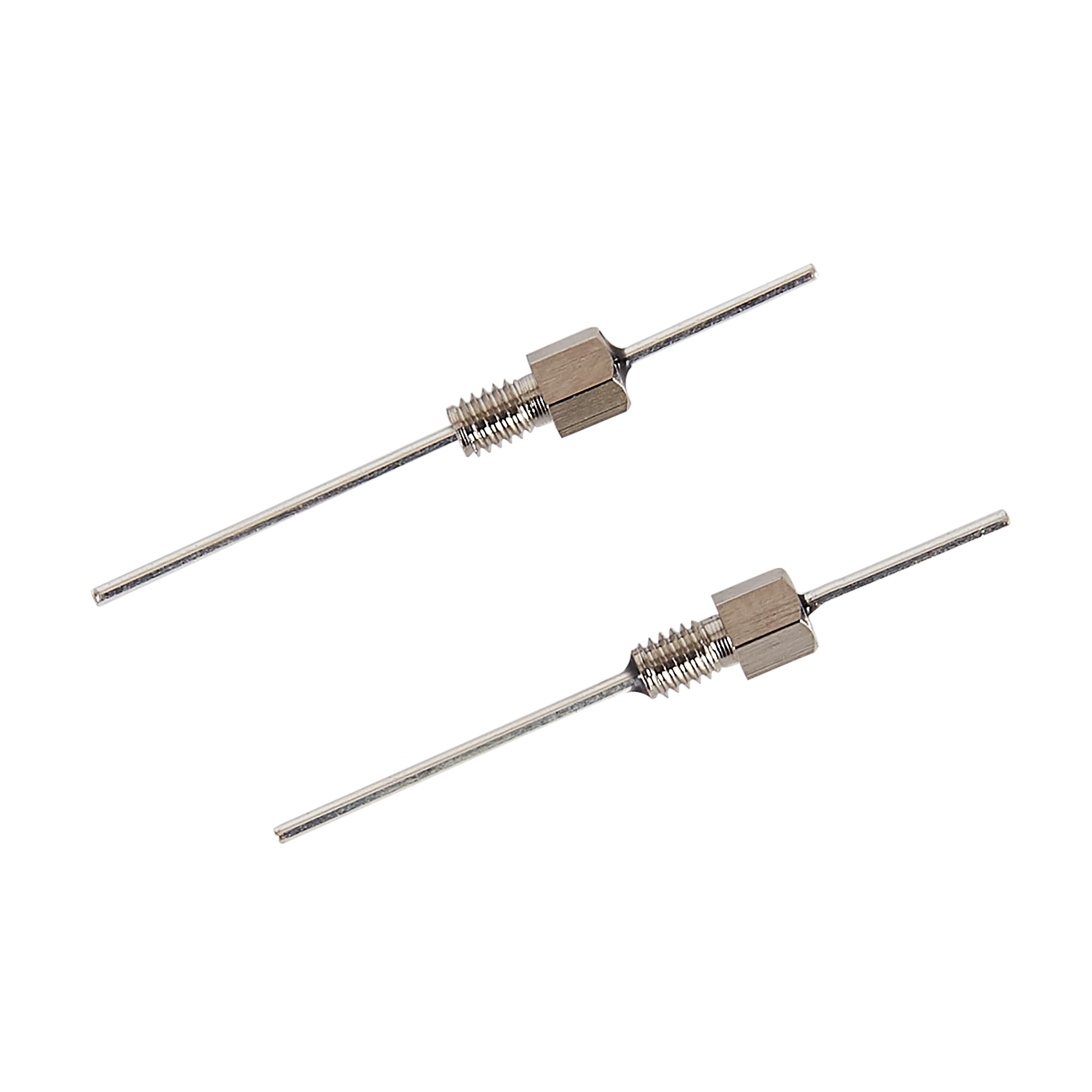
 Screw Type EMI FilterL3325 SeriesL4030 SeriesL5040 SeriesL5060 SeriesL6040 SeriesL6050 SeriesL8050 SeriesL8060 SeriesL9860 SeriesL10080 SeriesL1/4-28UNF-2A SeriesL4-40UNC-2A SeriesL5/16-24UNF-2A SeriesL5/16-32UNEF-2A SeriesL6-32UNC-2A SeriesL8-32UNC-2A SeriesL8-36UNF-2A SeriesL12-28UNF-2A SeriesL12-32UNEF-2A SeriesL140120 Series
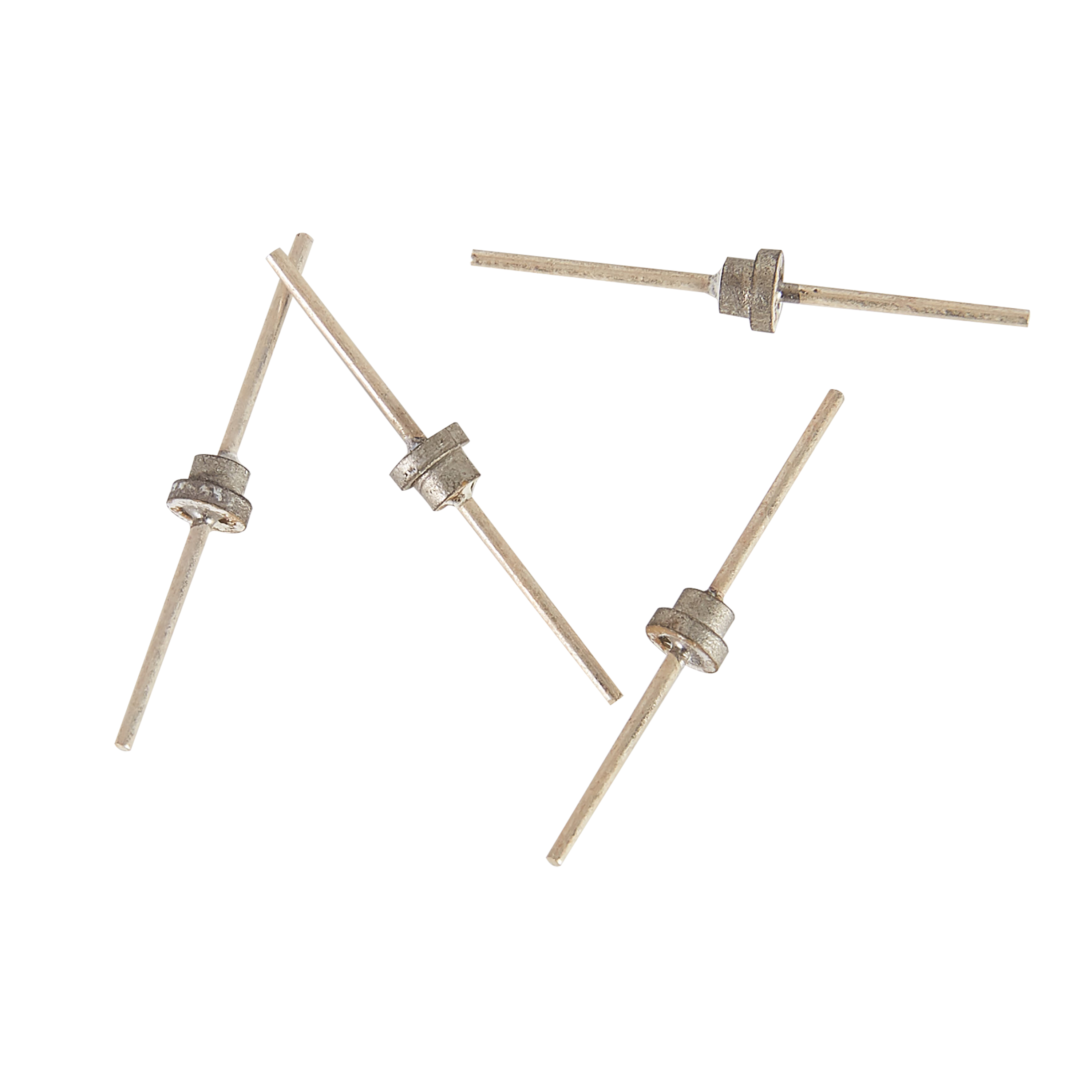 Solder Mount Feed-thru CapacitorH1915 SeriesH2222 SeriesH2416 SeriesH2519 SeriesH2520 SeriesH2618 SeriesH3630 SeriesH3822 SeriesH4033 SeriesH4224 SeriesH4330 SeriesH4532 SeriesH4722 SeriesH4737 SeriesH4743 SeriesH5038 SeriesH5122 SeriesHA4020 SeriesHB2020 SeriesT Series
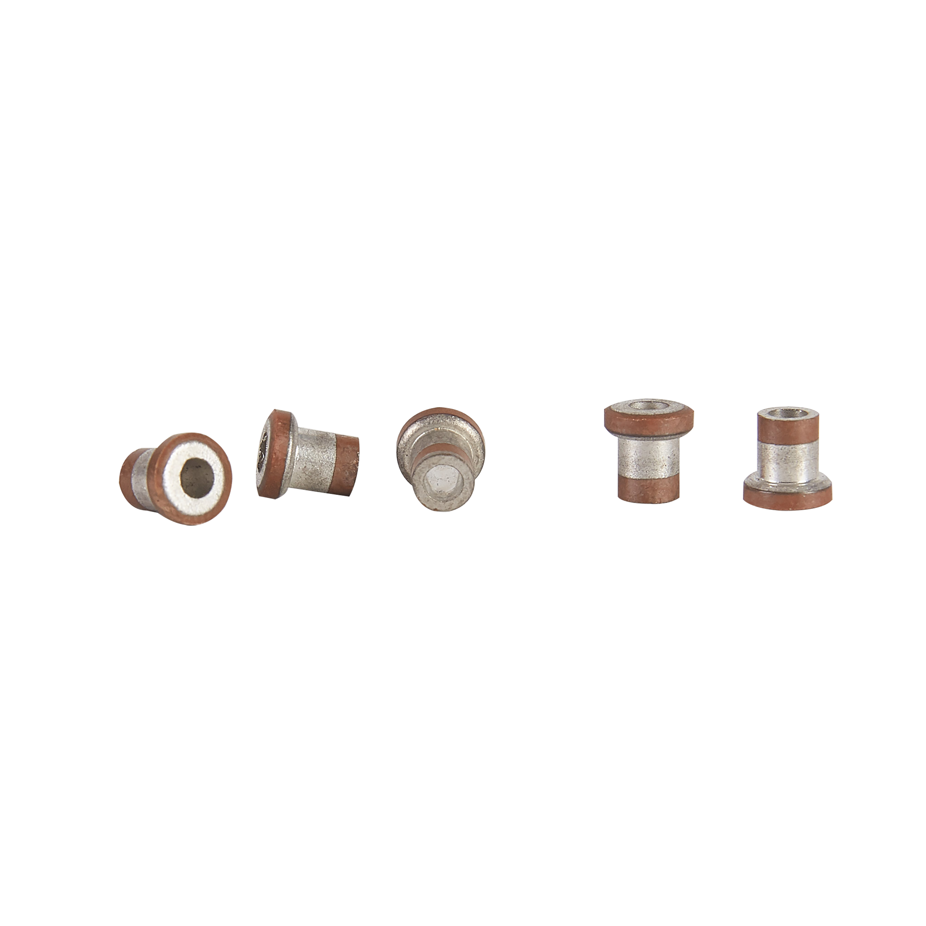 Tubular CapacitorG1915 SeriesG2020 SeriesG2222 SeriesG2416 SeriesG2520 SeriesG2618 SeriesG3822 SeriesG3838 SeriesG4224 SeriesG4330 SeriesG4532 SeriesG4722 SeriesG4737 SeriesG5038 SeriesG6045 Series
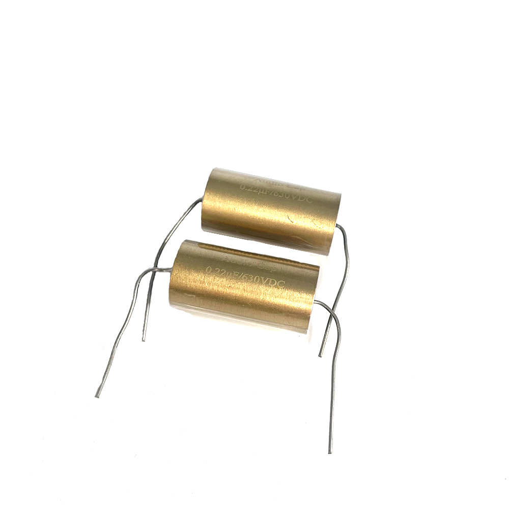 Audio Capacitor
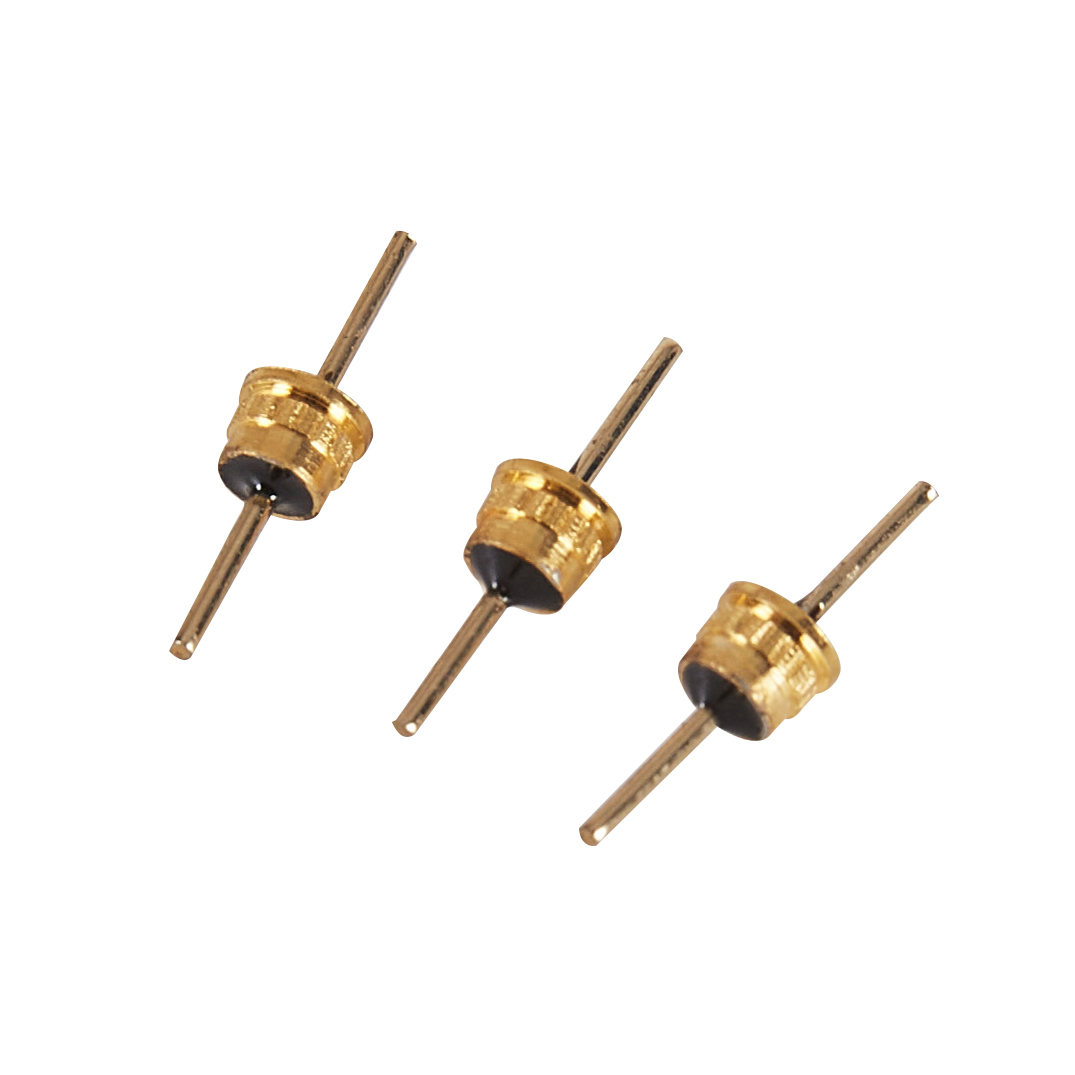 Q4033 Series
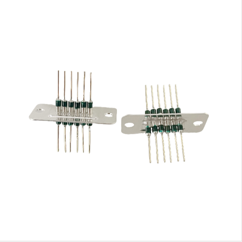 Filtered Array
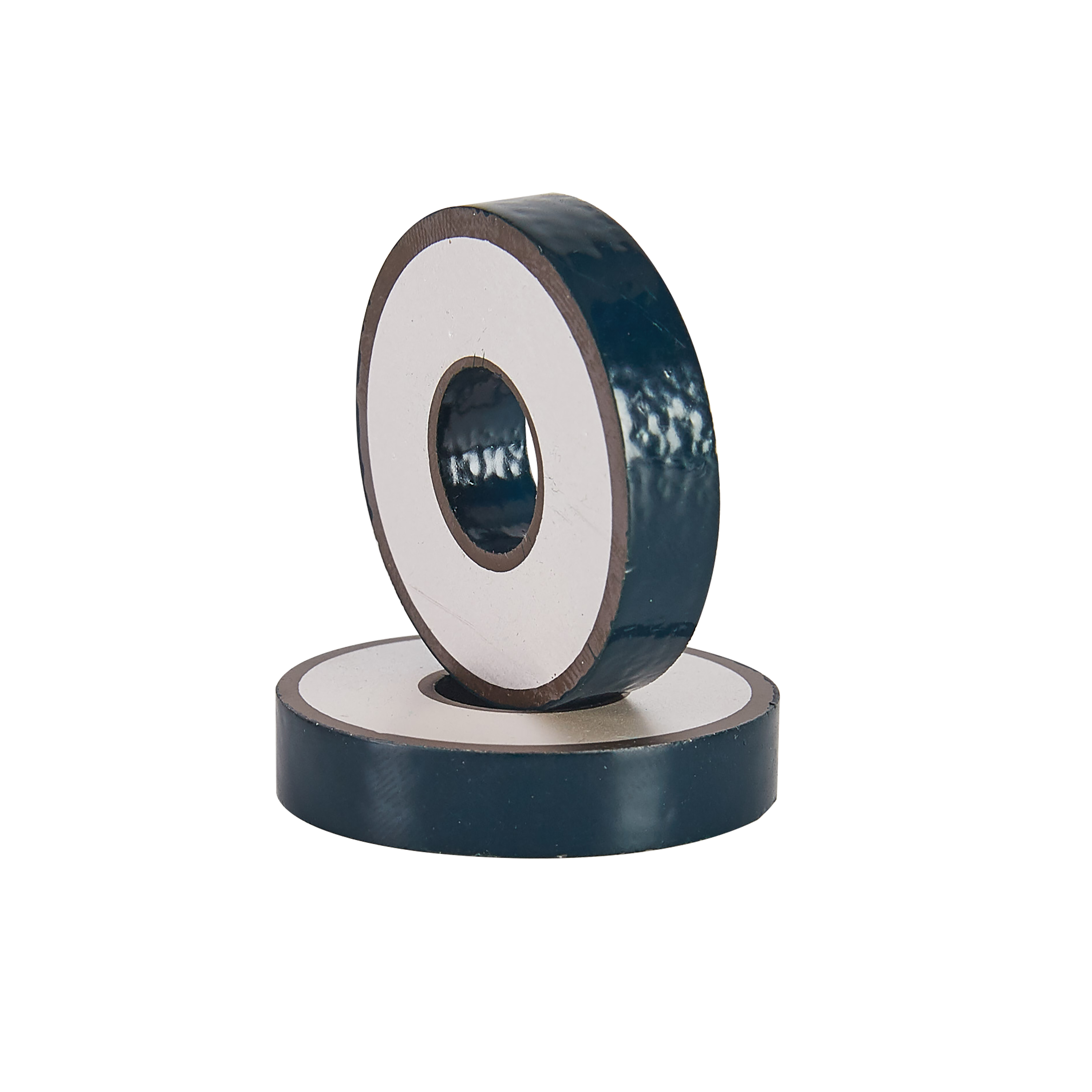 Discoidal Capacitor
 Screw Type EMI Filter
 Solder Mount Feed-thru Capacitor
 Tubular Capacitor
 Audio Capacitor
 Q4033 Series
 Filtered Array
 Discoidal Capacitor

Common experience and skills in electronic component testing 7106
Issuing time:2025-05-17 16:30 (1). Damage identification and detection of opto-couplers The multimeter should be set to resistor R x 100 instead of R x 10k to prevent the breakdown of the LED due to high battery voltage. Connect the red and black probes to the input terminal and measure the forward and reverse resistance. Normally, the forward resistance is several tens of ohms and the reverse resistance ranges from several thousand ohms to several tens of thousands of ohms. If the forward and reverse resistances are similar, it indicates that the LED is damaged. Select resistor R x 1 for the multimeter. Connect the red and black probes to the output terminal, measure the forward and reverse resistance, and ensure that they are both close ∞ under normal conditions. Otherwise, the light receiving tube will be damaged. Select resistor R x 10 for the multimeter, connect the red and black probes to the input and output terminals respectively to measure the insulation resistance between the light-emitting tube and the light receiving tube (if possible, use a megohmmeter to measure its insulation resistance, and the rated output voltage of the megohmmeter should be slightly lower than withstand voltage allowed by the tested opto-coupler. The normal insulation resistance between the light-emitting tube and light receiving tube should be ∞. (2). Damage discrimination and detection of photoresistors When testing, turn the multimeter to the R x 1kΩ position, keep the light receiving surface of the photoresistor perpendicular to the indicent light, and the resistance directly measured on the multimeter is the brightness resistance. Place the photoresistor in a completely dark place, and the resistance measured by the multimeter is the dark resistance. If the brightness resistance is several thousand ohms to tens of dry ohms and the dark resistance is several tens of megohms, it indicates that the photoresistor is good. |
